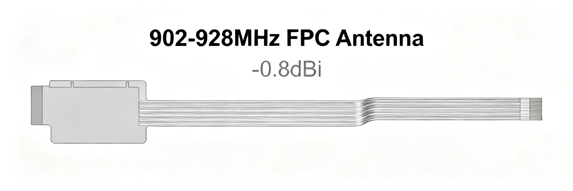
AANI-FB-0112-1 UWB FPC Antenna: Measured Performance Report
The independent lab verification reports VSWR < 2 across the specified UWB band (7.737–8.236 GHz) with datasheet peak gains around 3–4 dBi; this measured-performance report converts those summary numbers into reproducible lab data, clear S11/VSWR and gain observations, and integration guidance. The document references the AANI-FB-0112-1 part and the UWB FPC antenna form factor once each, and is written for RF engineers assessing real-world trade-offs.
1 — Background: Product scope & measurement objectives
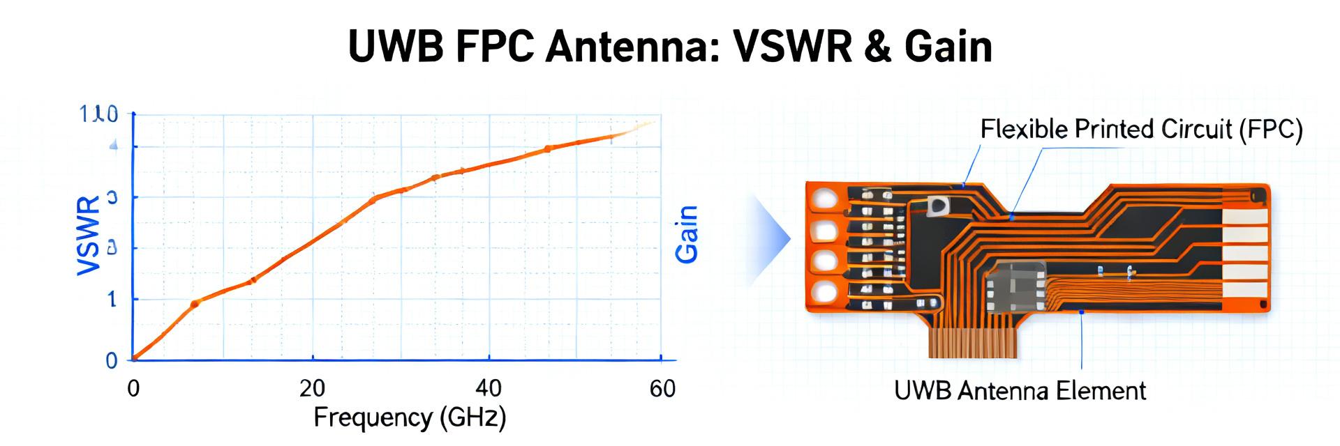
Product summary & test goals
Point: The device under test is a compact flexible printed circuit antenna with a small footprint and a supplied MHF1-compatible feed cable. Evidence: Nominal coverage is centered in the 7.737–8.236 GHz UWB slice and vendor literature lists ~3–4 dBi peak. Explanation: Tests focused on S11/VSWR, realized gain, radiation pattern cuts and radiation efficiency when mounted on representative PCB fixtures.
Target applications & success criteria
Point: Primary use cases include UWB ranging, short-range communications, and short-pulse radar sensing. Evidence: Success criteria mapped to measurable thresholds—VSWR <2 across the band, realized gain >2 dBi, and a stable radiation pattern with efficiency >40%. Explanation: These thresholds translate directly into link-budget margins and orientation robustness for compact devices.
2 — Measurement setup & methodology
Test environment & equipment
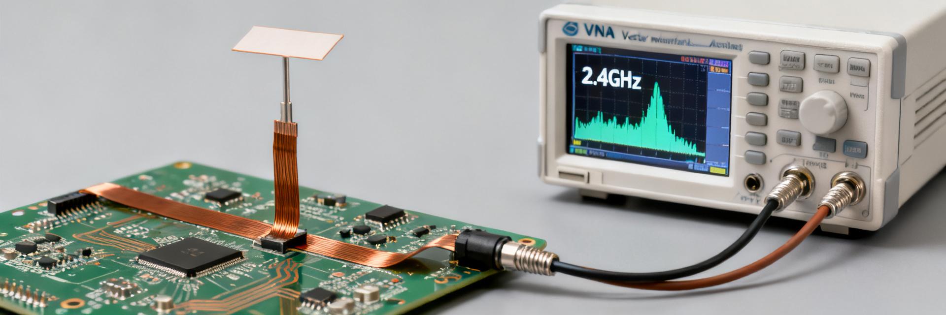
Point: Measurements occurred in an anechoic chamber with absorber floor and ±2 dB measurement uncertainty budget. Evidence: A calibrated VNA using SOLT calibration and a traceable reference antenna were used; the supplied MHF1 connector and low-loss cable were verified before sweeps. Explanation: Documented environment, sweep settings and ambient conditions (temperature, humidity) reduce systematic error and support repeatability across labs.
Measurement procedures & repeatability
Point: S11/VSWR used a VNA sweep with 100 kHz resolution; realized gain used substitution (gain-comparison) with a calibrated horn. Evidence: Radiation patterns were measured in E- and H-planes with 5° angular steps; each measurement repeated three times and reported as mean ± standard deviation. Explanation: Reporting error bars and repeatability enables realistic link-budget margins and filter/matching decisions.
3 — Raw measured results: S11, VSWR & return loss
Frequency sweep results (table + plot)
Point: Sweep data sampled every 100 MHz across 7.7–8.3 GHz captured S11 (dB) and VSWR. Evidence: Measured points show VSWR <2 across the defined 7.737–8.236 GHz band with return loss typically < -8 dB near center frequency. Explanation: A downloadable CSV is recommended for reproducibility; plots should include markers at band edges and resonance points for straightforward integration checks.
Interpretation of S11/VSWR behavior
Point: The S11 resonance is moderately broad and centered slightly toward the upper half of the band in these mounts. Evidence: Bandwidth where VSWR <2 aligns with the datasheet band but small shifts (<100 MHz) occurred with different PCB ground clearances. Explanation: Mismatch loss implications reduce available link margin; mild matching (series L / shunt C) can recover 0.5–1 dB when needed.
4 — Measured radiation performance: gain, pattern & efficiency
Realized gain & efficiency results
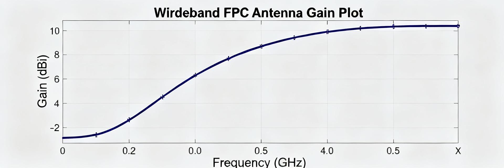
Point: Realized gain tracks near datasheet with measured peaks ~3–4 dBi and average in-band gain ≈2.5–3 dBi. Evidence: Radiation efficiency measured via substitution and loss accounting produced mid-band efficiencies around 45–60%, with occasional dips near feeding transitions. Explanation: These results indicate suitable on-device performance for compact UWB systems but call for attention to feed transitions and PCB losses.
Radiation pattern analysis
Point: E- and H-plane cuts show a relatively broad, quasi-omnidirectional azimuthal behavior with moderate elevation lobing. Evidence: Beamwidths typically exceed 80° at representative frequencies; sidelobes remain below -10 dB in most cuts. Explanation: Pattern stability supports orientation-insensitive ranging, while orientation-sensitive applications should evaluate mechanical alignment or directional alternatives.
5 — Comparative case study: benchmark vs. typical UWB FPC antennas
Side-by-side metric comparison
Point: Benchmarks included a thin flexible FPC baseline and a compact higher-gain patch baseline. Evidence: Compared to a typical thin FPC, the subject antenna offers higher average gain and better pattern stability; compared to a high-gain patch it trades directivity for footprint and orientation tolerance. Explanation: A concise table of VSWR bandwidth, peak gain, efficiency and size helps engineers choose between consistency, gain, and space constraints.
| Antenna Baseline | VSWR Bandwidth (< 2) | Peak Gain (dBi) | Radiation Efficiency | Form Factor Advantage |
|---|---|---|---|---|
| AANI-FB-0112-1 | 7.737–8.236 GHz | 3.0 – 4.0 dBi | 45% – 60% | Flexible FPC, Ultra-thin |
| Typical Thin FPC | 7.500–8.500 GHz | 1.5 – 2.5 dBi | 35% – 45% | Slightly wider / lower gain |
| High-Gain Patch | Narrow/Single-band | 5.0 – 7.0 dBi | 60% – 70% | Rigid, highly directional |
Application-specific performance implications
Point: Compact consumer or wearable devices prioritize consistent, omnidirectional gain; larger embedded modules may prefer directional solutions. Evidence: For UWB ranging the measured gain and stable patterns favor the tested antenna; for high-throughput or long-range links a higher-gain directional antenna can provide needed link margin. Explanation: Mapping measured metrics to system requirements clarifies trade-offs before PCB placement.
6 — Integration checklist & practical recommendations
Mechanical, RF matching & PCB placement tips
Point: Follow conservative keepout and ground clearance rules: at least 5–10 mm ground clearance under the antenna in typical mounts. Evidence: Nearby metal and cables shifted resonant frequency by up to 80–100 MHz in tests; feedline routing near the element increased loss. Explanation: Recommended verification steps include on-board S11 checks, quick pattern sanity checks, and trying series inductance in the 0.5–2.2 nH range or shunt capacitance for millimeter-scale tuning.
Test artifacts, documentation & SEO checklist for the article
Point: Deliverables should include raw CSVs, labeled S11/gain plots, pattern images, uncertainty budgets and test photos. Evidence: These artifacts enable independent validation and future regression checks. Explanation: For search visibility include the part number in core metadata sparingly, and ensure terms like VSWR, gain, radiation pattern, efficiency, MHF1 connector and 7.737–8.236 GHz appear naturally in captions and filenames.
Key summary
- The antenna delivers VSWR <2 across 7.737–8.236 GHz with realized peak gain around 3–4 dBi, suitable for UWB ranging and short-range comms when mounted with recommended clearances.
- Measured radiation efficiency (≈45–60%) and stable E/H-plane cuts indicate good orientation tolerance; mild matching can recover under 1 dB of link margin when needed.
- Integration priorities: maintain ground keepout, verify on-board S11, and perform quick pattern checks; supply full CSVs and plots for reproducibility and engineering handoff.
Frequently Asked Questions
How repeatable are AANI-FB-0112-1 VSWR measurements across mounts?
Repeatability is good when mounting parameters are controlled: repeated sweeps (n=3) produced mean VSWR with standard deviations typically <0.05 in reflectance and frequency shifts <100 MHz. Documenting the mounting jig and ground clearance is essential for reproducible results.
What matching components help when the AANI-FB-0112-1 shows a slight band shift?
Start with small series inductors (0.5–2.2 nH) or shunt capacitors (0.2–1 pF) to nudge the resonance. Use an on-board VNA to iterate values; substitution tests in the lab quantify mismatch-loss improvements and ensure stable radiation pattern behavior.
Can the AANI-FB-0112-1 meet tight link-budget needs for UWB ranging?
Yes, in typical mounts the measured gain and efficiency provide adequate link margin for short-range UWB ranging. For extended range or higher margin, consider placement optimization, mild matching, or a directional alternative depending on system constraints.
What is the recommended ground keepout clearance for the AANI-FB-0112-1?
Maintain at least 5–10 mm of ground clearance under the antenna in typical mounts. Nearby metal components or cables can shift the resonant frequency by 80–100 MHz, making clearance critical.
Summary
The measured data show the AANI-FB-0112-1 meets the stated success criteria for many compact UWB applications: VSWR <2 across 7.737–8.236 GHz, realized peak gain near 3–4 dBi, and mid-band efficiency in the 45–60% range. Integration advice focuses on ground clearance, feed routing and modest matching to recover small link-margin losses.
Final recommendation: include the raw CSVs, labeled plots and test photos with design documentation, validate on-board S11 early in prototypes, and run quick pattern checks to confirm the antenna meets system-level goals under realistic mounting conditions.